
Groundwater Flow Modeling
| PROJECT NAME & LOCATION | DATE STARTED | DATE COMPLETED | |||||
| Pennridge Wellhead Protection, Bucks Co. PA |
January, 2005 | May, 2007 |
| ACTIVITY TITLE | APPROXIMATE CONTRACT VALUE | |||
| Geological & Groundwater Flow Modeling | $85,000 |
| CLIENT NAME & ADDRESS | TECHNICAL CONTACT | |||
| Borton Lawson Engineering Wilkes-Barre, PA (570) 821-1999 |
Dennis Livrone - Bucks Co. Planning (215) 345-3422 dplivrone@co.bucks.pa.us |
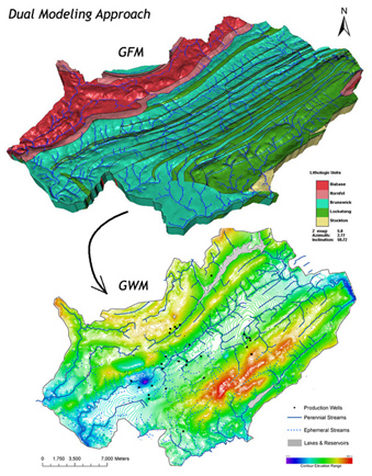
(Top) Geologic framework defining the 3D orientation of 60 dipping interbedded stratigraphic units intruded by an igneous dike and dissected by streams.
(Below) Simulated groundwater flow field based on the hydrostratigraphic framework from the GFM and hydraulic conditions created by streams, quarry dewatering, and municipal groundwater pumping.
GeoHydros successfully generated rapidly updatable, very high resolution, 3D models (0.05 foot vertical
interval) of soil contamination that were considered by the project management and the regulatory agency to significantly expedite an effective rapid site characterization (Triad) approach that saved money and time and facilitated better decision making.
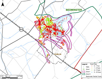
Delineation of standard EPA Zone II WHP boundaries (purple line) as defined by 2D particle tracks and alternate Zone II boundaries (colored points) defined by 3D particle tracks intersecting the bedrock surface.
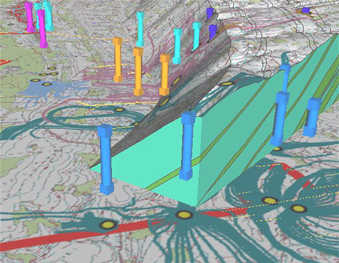
Orientation of water bearing (blue) and confining units (green) relative to the position and depth of municipality water supply wells and the well capture zones simulated in FEFLOW.
Deliverables included: (1) delineation of wellhead protection zones based on 3D particle tracks, (2) incorporation
of model results & wellhead protection zones into appropriate ordinance language, (3) four quarterly presentations to the Municipality authorities and project management on the status and results of the modeling effort, and (4) a final report on model development, calibration, results, and wellhead protection zone delineation. in a synclinal basin, faulted at one end, and then intruded by the diabase.
GeoHydros successfully developed a regional 3D model of groundwater flow bounded by established no-flow boundaries. The model was developed with sparse data but calibrated well to water levels measured in 19 municipal groundwater supply wells under both static and pumping conditions. Particle tracks exported from the pumping conditions model were used to define well capture zones that were, in turn used to delineate standard EPA Zone II WHP boundaries for all the well fields. The modeling, particle track exports, and reporting were all completed on time and on budget. After the modeling was completed and our budget exhausted, we continued to support the project during a lengthy public review and comment period. Part of that support included developing an alternative set of Zone II boundaries that encircled the recharge areas for the wells as defined by the intersection of 3D particle tracks with the bedrock surface. In the end, the model was well received and the Pennsylvania Department of Environmental Protection stated that it marked a new standard for wellhead protection projects in Pennsylvania.